The honest answer up front Key takeaways Why LiFePO4 cutoffs differ from lead-acid The voltage flat-plateau problem Recommended cutoffs by system voltage Inverter settings vs BMS Sag, alarms, and false shutdowns Cold weather: charging vs discharging FAQ
The honest answer up front
For a 12V LiFePO4 bank, set your inverter’s low-voltage cutoff around 11.5V resting (roughly 10% capacity remaining) — not the 10.5V you’d use for lead-acid, and not the 9–10V the BMS will eventually enforce. Scale by multiples of that for 24V (23.0V) and 48V (46.0V).
The reasoning is asymmetric: LiFePO4 stores almost nothing below its flat plateau, so cutting off early costs you a rounding error of energy — but over-discharging even occasionally measurably shortens cycle life. The cheap insurance is a conservative setpoint. The BMS will still protect the cells at a lower threshold as the backstop; your job is to make sure it never has to.
The one setting most people get wrong: using lead-acid numbers on lithium (too low, stressing the cells) or copying a random forum chart without checking whether the voltages were measured under load or at rest. Those two contexts differ by half a volt or more — the whole section on sag explains why.
Key takeaways
- Resting vs under-load voltage are different numbers. A bank at 12.0V resting is nearly empty; at 12.0V under heavy inverter load it may be half full.
- 11.5V (12V system) resting is a sane daily cutoff; the BMS hard floor (typically ~10V) is emergency protection, not a routine.
- Scale linearly: 23.0V for 24V banks, 46.0V for 48V banks.
- Surge vs continuous: a microwave starting can dip voltage below your cutoff for milliseconds — set the inverter’s alarm lower than its shutdown, or accept false trips.
- Cold changes charging, not discharging. Discharge cutoffs barely move with temperature; charging below freezing is what destroys lithium cells (the BMS should block it; verify it does).
Why LiFePO4 cutoffs differ from lead-acid
Lead-acid voltage falls gradually and predictably as it discharges — you can eyeball state of charge from a voltmeter to within ~20%. Its safe cutoff (10.5V for a 12V monoblock) is chosen to avoid sulfation and permanent capacity loss.
LiFePO4 behaves differently at both ends of the curve:
- The discharge curve is a cliff, not a slope. From 90% down to ~15% state of charge, a 12V LiFePO4 bank sits between about 13.2V and 12.9V — a 0.3V window representing most of the battery’s usable energy. Then it drops steeply. Voltmeter-as-fuel-gauge simply doesn’t work in the plateau; see the section below.
- There’s little energy below the cliff anyway. Discharging from 11.5V to the BMS floor recovers a few percent of capacity while stacking damage on the cells. It’s the worst trade in the whole system.
- Cycle life is the whole value proposition. LiFePO4’s economics rest on 3,000–6,000+ cycles — but that figure assumes sane depth of discharge. Ride the BMS floor daily and you’re buying an expensive battery with lead-acid longevity.
The voltage flat-plateau problem
Here’s what a 12V LiFePO4 bank’s resting voltage looks like across a discharge:
| State of charge | Resting voltage (approx.) |
|---|---|
| 100% (full, settled) | 13.3–13.6V |
| 90% | ~13.2V |
| 50% | ~13.0V |
| 20% | ~12.8V |
| 10% | ~12.5V |
| 0% (BMS floor territory) | <11.0V, falling fast |
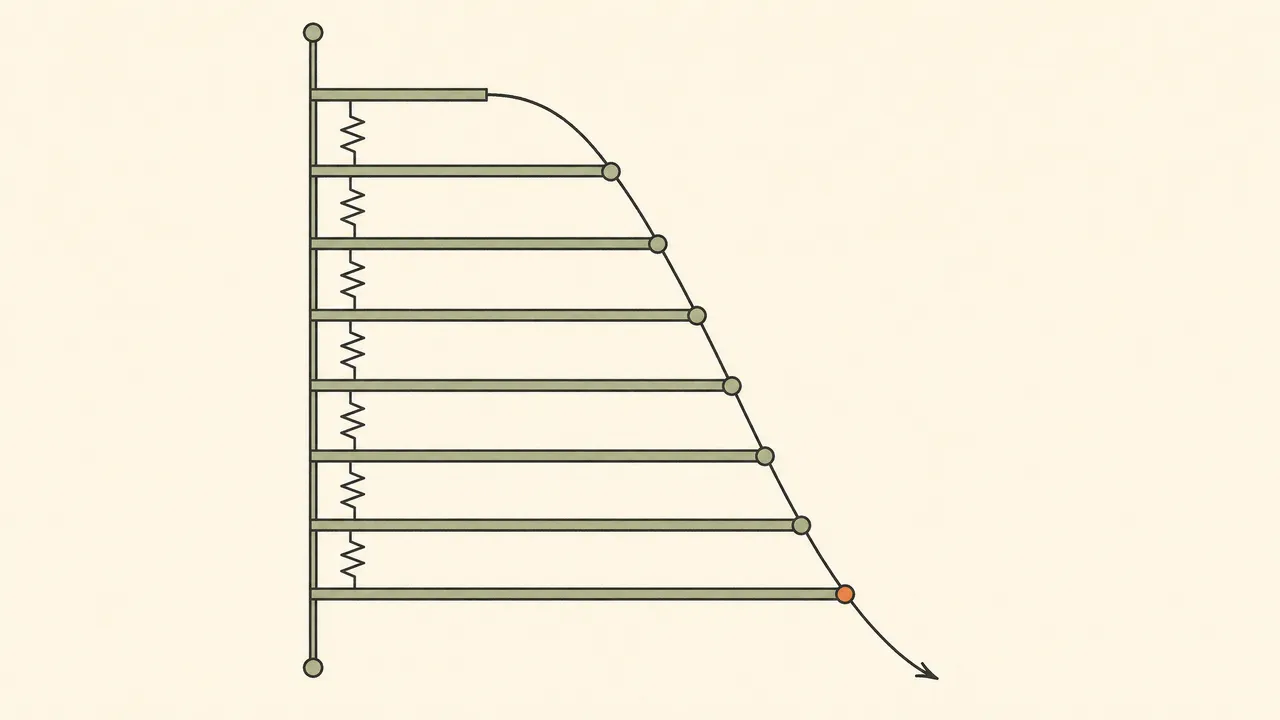
Two consequences:
- You cannot use voltage as a state-of-charge gauge in the plateau. 13.0V tells you “somewhere between 20% and 90%.” If you need real state of charge, you need a coulomb-counting (shunt-based) battery monitor — voltage alone cannot do this job for lithium.
- The cutoff is a cliff-edge fence, not a fuel gauge. You’re not reading “how much is left” from voltage; you’re catching the bank before it goes over the edge where damage begins.
Recommended cutoff settings by system voltage
Honest numbers, resting voltage, typical LiFePO4 (4 cells in series per 12V):
| System | Daily cutoff (resting) | Alarm (under load) | BMS floor (typical, not a setpoint) |
|---|---|---|---|
| 12V | 11.5V | 11.8–12.0V | ~10.0V |
| 24V | 23.0V | 23.6–24.0V | ~20.0V |
| 48V | 46.0V | 47.2–48.0V | ~40.0V |
Three honest caveats:
- Your battery’s manual outranks this table. Manufacturers publish their own cutoff and recovery voltages; cells and BMS behavior vary by brand and grade.
- “Resting” means no significant load for 15+ minutes. Setting an inverter to disconnect at 11.5V under load will trip it early every heavy-use evening — that’s what the alarm column is for.
- Recovery/hysteresis matters. After a cutoff, the bank’s voltage rebounds. If your inverter reconnects loads at the same voltage it disconnected at, it will oscillate on/off. Set recovery at least 0.5–1.0V higher (12V basis).
Inverter settings vs BMS: two different jobs
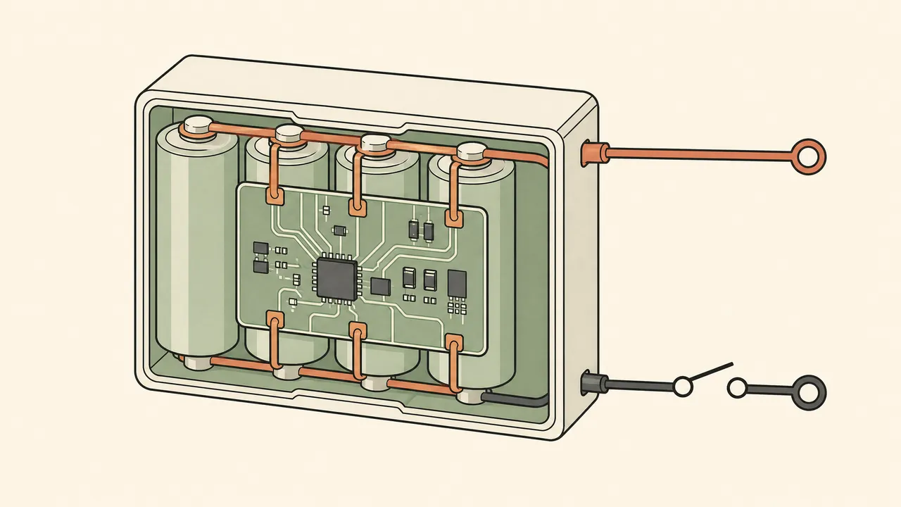
The division of labor:
- The inverter’s LVC is your daily setpoint. It should trip first, cleanly, at a voltage that preserves cycle life. You control it; it’s the front door.
- The BMS floor is emergency protection. It trips when something has already gone wrong — a failed inverter setting, a forgotten load over a cloudy week, a cell imbalance dragging one cell down while the pack voltage still looks fine. It’s the backstop, and its shutdown is abrupt: loads drop now, with no warning ramp.
- Relying on the BMS as your daily cutoff is a habit that costs money. Every deep excursion toward the floor stresses the weakest cell; the pack ages at the pace of its most-abused cell. If your logs show frequent BMS events, fix the settings — don’t normalize the fence doing the door’s job.
One more trap: a BMS disconnect under load can look like a dead system. The inverter shows a wild low-voltage reading (or nothing), the battery shows no voltage at the terminals, and people buy a new battery when the old one just needs a wake-up charge or a reset. Check the manual for the wake procedure before concluding death.
Sag, alarms, and false shutdowns
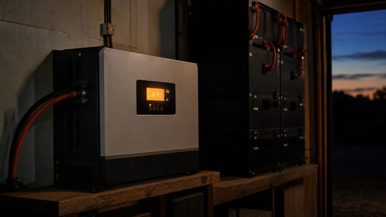
Voltage sag is the transient dip when a big load starts: a microwave, a well pump, a table saw, an air conditioner compressor. The bank’s internal resistance plus cable resistance subtracts volts in proportion to current — for milliseconds to seconds.
The practical recipe:
- Set the alarm voltage ~0.3–0.5V above the shutdown (12V basis). You hear the beep, know a heavy load started, and ignore it — or shed load if it persists.
- If you get false shutdowns on motor starts, either raise the shutdown slightly, enable the inverter’s surge-override window if it has one, or fix the real problem: undersized cables or a weak connection adding resistance. Sag from thin wire is the most common root cause we see (cable math: battery cable sizing for inverters).
- Distinguish sag from empty. Sag recovers the moment the load drops; empty doesn’t. If voltage rebounds to 12.8V+ after the microwave finishes, your bank wasn’t low — your alarm threshold was, or your cables are.
Cold weather: charging vs discharging

The asymmetry that matters:
- Discharging when cold is safe but weaker. Available capacity and current both drop with temperature; your bank acts smaller in January. The cutoff voltage barely moves — don’t retune it for winter.
- Charging below 0°C (32°F) causes plating damage — lithium plates onto the anode, permanently reducing capacity and, in bad cases, creating internal short risk. Quality BMS units block charging when cell temperature is below freezing; cheaper ones only sense pack temperature (which lags).
- Self-heating batteries solve this with a heater that runs before allowing charge — if your bank lives outside or in an unheated space in freeze territory, this feature is worth its premium (see charging LiFePO4 below freezing).
The failure signature to know: system “works all winter” then loses capacity in spring — classic low-grade cold-charging damage from a BMS that blocked fast charging but let small float currents through, or from charging a battery whose cells were cold while its case sensor read warm.
On the flat LiFePO4 plateau, voltage can't tell you what's left — a shunt-based coulomb counter can, and this one reports to your phone with no display to wire (per manufacturer spec). Not for: banks you never look at — data you don't read is money spent anyway. The honest tradeoff: it counts amp-hours, so accuracy drifts if you don't let it resync at a full charge now and then.
Check price on Amazon (opens in a new tab) Price & availability shown on Amazon.com — we may earn a commission.The full-function sibling: shunt counting plus a real display, relay output, and temperature input — useful when you want the monitor to drive alarms or logging without a phone (per manufacturer spec). Not for: minimal installs where the SmartShunt already covers it. The honest tradeoff: more money and more wiring for features a simple setup may never use.
Check price on Amazon (opens in a new tab) Price & availability shown on Amazon.com — we may earn a commission.FAQ
What is the correct low-voltage cutoff for a 12V LiFePO4 battery?
Why does my inverter shut off when the battery still shows charge?
Can I use the BMS as my low-voltage cutoff?
Does cold weather change the low-voltage cutoff?
Why is my battery showing 0V?
Next logical reads
Li-ion vs lead-acid Battery management systems explained Charging LiFePO4 below freezing Batteries in series vs parallel Battery cable size for inverters Inverter keeps shutting off Solar battery monitoring guide